Quick answer: A cadence sensor detects crank rotation; a torque sensor measures pedalling effort. Both can be used for pedal assistance, but the controller and software determine the response. Choose a sensor that matches the bike’s mechanical interface and the controller’s electrical input, calibration and safety settings.
For conversion-kit workshops, distributors and OEM buyers, the choice is about the complete system rather than a sensor label. This guide compares the two approaches and lists the information needed to specify a compatible installation.
1. What is pedal assist?
A pedal assist system (PAS) uses pedalling input to request motor assistance. Depending on the design, that input can include cadence, torque or both. A throttle is a separate rider input; the presence of a throttle does not, by itself, determine a bike’s legal classification.
Assistance should behave according to the approved system settings and applicable rules. Start response, stop response, walk assistance and any throttle function must be evaluated separately rather than inferred from the sensor type.
2. Cadence sensors versus torque sensors
| Factor | Cadence sensing | Torque sensing |
|---|
| Measured input | Whether and how fast the cranks rotate; some designs also detect direction. | Pedalling load, often combined with cadence information. |
| Typical feel | Can provide assistance with light pedalling; response depends on controller tuning. | Can scale assistance with rider effort when the system is configured to do so. |
| Integration | Often a magnet ring and pickup, or an integrated unit. | May be integrated into a motor, bottom bracket or another sensing assembly. |
| Buyer priorities | Cost, mounting space, direction detection and start/stop behaviour. | Mechanical fit, signal compatibility, calibration and desired response. |
| Limitations | Magnet count alone does not guarantee smooth or immediate assistance. | The word “torque” does not guarantee zero lag or compatibility with an existing controller. |
Choose by the intended riding experience and verified system response. Commuting, accessible low-effort riding, cargo duty and technical off-road use can place different demands on a build. Neither sensing method automatically guarantees more range or road legality.
3. Understand the hardware options
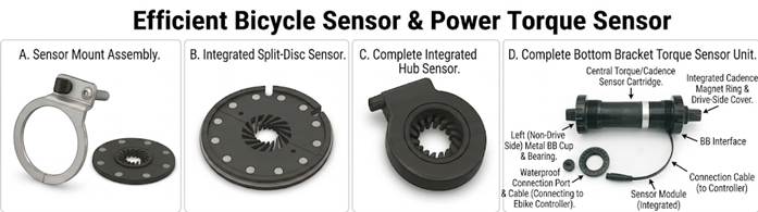 Illustrative hardware categories only. Labels and drawings are not model-specific installation or wiring instructions.
Cadence sensor assemblies
Common arrangements include a separate magnet disc and pickup or an integrated sensing unit. A split magnet ring may reduce disassembly for some installations, but not every sensor or disc can be fitted without removing the crank. Check the actual model’s instructions.
Magnet count affects the signals available to the controller. More magnets can provide more pulses per revolution, but start-up behaviour also depends on firmware thresholds, direction detection, alignment and processing. Do not promise a fixed quarter-turn or half-turn response without testing the system.
Torque-sensing assemblies
Torque sensing may be integrated into a mid-drive motor or provided by a bottom-bracket assembly used with a compatible hub-motor control system. A hub motor does not rule out torque-based assistance, and a mid-drive motor is not automatically torque-sensing.
Ask whether the unit measures one side or both sides and how the controller processes the signal. Do not assume that a dual-sided label guarantees perfectly uniform output or that a sensor can be added by changing only the plug.
4. Check mechanical compatibility
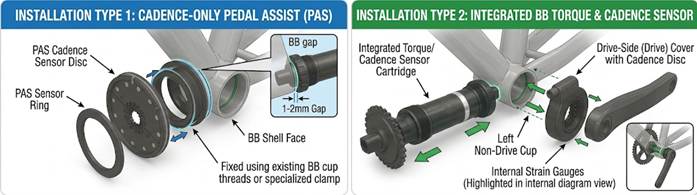 Conceptual comparison only. Any printed gap or dimension is not a specification for your bicycle; follow the exact component and frame instructions.
| Mechanical detail | What the buyer should confirm |
|---|
| Bottom-bracket interface | Threaded or press-fit standard, thread details and installation requirements. |
| Shell width and spindle length | Actual measured dimensions and the sensor or motor’s supported range. |
| Crank interface and chainline | Compatibility with the crankset, chainring, drivetrain and chainstay clearance. |
| Sensor side and clearance | Approved drive/non-drive-side installation, magnet orientation and model-specific sensing gap. |
| Cable route and mounting | Strain relief, moving-part clearance, water exposure and service access. |
Widths such as 68mm or 73mm occur on many threaded bicycle bottom brackets, while some wide frames use different dimensions. These examples are not a fit guarantee. Identify the frame and crank interface before buying; do not replace a modern crankset with a square-taper system unless the complete conversion has been checked.
5. Match the signal and controller
Matching connector shape, colour or pin count is not enough. Confirm supply voltage, ground, signal type, pinout, direction information and whether the controller accepts that sensor. Some controllers accept cadence only; others need a specific torque sensor or an intermediate control device.
Obtain the controller and sensor model numbers and their compatibility documentation.
Confirm the sensor supply requirement and each pin’s function from the manufacturer’s drawing.
Check whether the signal is pulse-based, analogue or digital and whether calibration is required.
Verify display and firmware settings as part of the complete system.
Disconnect the battery before connecting, disconnecting or inspecting accessible plugs; do not force or re-pin a connector without an authorised procedure.
Never assume a universal 5V supply, colour-coded pinout or plug standard. An incorrect connection can damage components. Have a qualified technician resolve missing documentation rather than testing unfamiliar live wiring.
6. Configure and test assistance safely
Install using the exact model’s fastener torque, alignment and cable-routing instructions.
Configure the documented sensor type, direction and pulse settings where the controller requires them.
Carry out any zero-point or load calibration specified by the manufacturer, without pressure on the pedals unless instructed otherwise.
Check start, stop and brake-cut-off behaviour in a controlled test environment before riding.
Confirm wheel rotation cannot injure anyone during a workshop check; do not test unexpected acceleration in traffic.
Do not apply a generic bottom-bracket installation torque such as 35–45Nm to every sensor. Tightening and calibration procedures are model-specific. Stop testing if assistance appears without the intended input, continues unexpectedly or responds erratically.
7. Troubleshoot with the system documentation
| Symptom | Checks before further testing |
|---|
| No assistance | Battery/controller state, enabled assist level, brake-cut-off status, documented sensor compatibility and accessible connection security. |
| Delayed or inconsistent assistance | Disc alignment, mounting direction, supported pulse settings and the model-specific sensing gap. |
| Unexpected assistance or backpedal activation | Stop use; check direction configuration and the approved sensor/controller pairing with a technician. |
| Torque assistance feels weak or unstable | Approved calibration, installation procedure, mechanical fit and whether the controller reads the intended signal. |
These are diagnostic starting points, not fault confirmations. Do not compensate for a wiring or compatibility problem by increasing current limits, defeating brake cut-offs or disabling protective functions.
8. Check the rules for the destination market
Sensor choice alone does not make a conversion road-legal. Requirements may concern continuous rated power, assistance cut-off, pedal operation, throttle functions, vehicle approval and where the bicycle may be used.
For Great Britain, the government’s EAPC guidance sets out the applicable pedal, power and assistance-speed conditions, with separate considerations for some throttle-capable vehicles. In the EU, the pedal-assist exclusion in Regulation (EU) No 168/2013 has its own conditions. North American requirements vary by jurisdiction. Check the current local rules for the complete vehicle rather than applying one global “6km/h throttle” rule.
Pedal-assist FAQ
Can I replace a cadence sensor with a torque sensor?
Sometimes, but only if the mechanical fit and controller/control interface support it. A plug adapter or matching pin count does not establish compatibility.
Do all mid-drive motors use torque sensing?
No. Confirm the exact motor’s sensing and control method. Motor position alone does not identify the assist system.
Will a higher magnet count always remove start-up delay?
No. Magnet count is one input. Alignment, direction detection, firmware and the assistance algorithm also affect response.
What should I provide when requesting a PAS configuration?
Provide the bike and frame interface, bottom-bracket dimensions, crank type, motor/controller/display models, existing sensor, desired assist behaviour and destination market. Send the component documentation where available.
Discuss a compatible conversion system
Explore hub motor kits and mid-drive kits, or read the motor selection guide and controller compatibility guide. Contact ECOWAY TECH with the actual component models before choosing a sensor.
Sources and further reading

