An ebike controller manages the electrical power sent from the battery to the motor. It responds to the throttle or pedal sensor, controls how assistance feels, and can reduce or stop motor output when a protection function is triggered. Choosing the right controller means matching the battery, motor, display and wiring—not simply selecting the highest amp rating.
This guide explains square wave and sine wave controllers, current ratings, display protocols, connectors and common features in everyday language. It is intended for riders and buyers comparing electric bicycle components or conversion kits.
What does an ebike controller do
Think of the battery as the energy store, the motor as the part that moves the bike, and the controller as the unit that regulates power delivery. A well-matched controller helps the bike start predictably and respond smoothly when you change the throttle position or pedal harder.
Regulates motor output according to rider input and the selected assistance level.
Coordinates inputs from components such as the display, pedal sensor and brake switches.
Provides model-dependent protection, such as low-voltage cut-off, current limiting and temperature protection.
Ride quality depends on the complete system. The motor, sensors, battery capability and controller settings all matter.
Sine wave vs square wave controllers
Square wave controllers generally use a simpler, lower-cost approach to driving the motor. Some setups feel more direct or abrupt when starting. This does not automatically make them more powerful.
Sine wave controllers generally produce smoother motor operation and less electrical motor noise when matched and tuned correctly. They are often chosen for comfortable everyday riding.
Comparison | Square wave | Sine wave |
Motor sound | May be more noticeable | Usually quieter |
Starting and acceleration | Can feel more direct | Usually smoother |
Typical cost | Often lower | Often higher |
Common priority | Basic performance and cost | Comfort and quiet operation |
Neither type is automatically faster or more efficient in every situation. Ask how the complete bike performs under your expected load and riding conditions. FOC, or field-oriented control, is another term you may see; it describes a method of controlling the motor more precisely, rather than a guaranteed power level.
How to read an ebike controller label
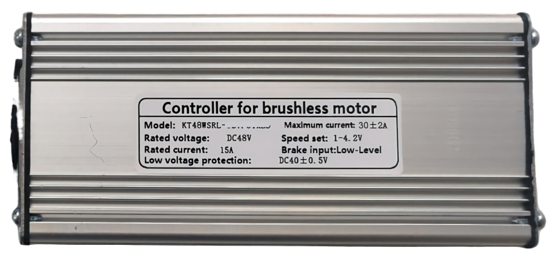
Example controller label. Ratings apply to this unit, not to every controller with a similar housing.
Model and rated voltage
The model identifies the controller version or product family. A serial number or batch code is a separate identifier; the manufacturer may need it to confirm the exact hardware and software version.
Rated voltage describes the battery system the controller is designed to work with. Common examples include 36 V, 48 V, 52 V, 60 V and 72 V. Confirm the permitted battery voltage range and low-voltage cut-off with the supplier. Nominal battery voltage and fully charged voltage are different values.
Rated current and maximum current
Rated current is the current the manufacturer specifies for normal continuous operation under stated conditions. It is not the current the bike draws all the time. Maximum current is the controller’s stated upper current limit; how long it can operate near that limit depends on the design, settings and cooling.
The example label shows a rated current of 15 A and a maximum current of 30 A, with a stated tolerance. These values happen to have a two-to-one relationship. Other controllers can have different relationships, so always read the actual specification.
Ask whether a current rating refers to battery current or motor phase current. They are different measurements and should not be compared as if they were the same.
MOSFET count and motor power
MOSFETs are electronic switches inside the controller. A listing such as “6-MOSFET” or “12-MOSFET” describes how many switches are used. The count alone cannot tell you the rated current, maximum current or suitable motor power.
The following illustrative combinations show how controller listings can vary. They are not a universal sizing chart or an Ecoway product specification. Check the exact controller model and battery voltage before using any pairing.
MOSFET count | Rated current | Maximum current | Example motor pairing |
6 | About 7 A | About 15 A | 250–350 W |
6, higher-current version | About 8 A | About 17 A | 350 W |
9 | About 11 A | About 22 A | 500 W |
9, higher-current version | About 12 A | About 25 A | 750 W |
12 | About 15 A | About 30 A | 1000 W |
12, higher-current version | About 17 A | About 35 A | 1500 W |
Battery voltage multiplied by battery current gives an approximate electrical input power. For example, 48 V × 15 A is about 720 W of input at those values. This is not the motor’s mechanical output or proof of its continuous rated power. A motor pairing advertised as “1000 W” does not change that calculation.
A controller with 15 MOSFETs therefore has no single standard current or motor-power rating. Request its data sheet instead of choosing by MOSFET count.
UART and CAN vs display protocol names
The controller and display need to communicate using compatible rules. UART and CAN describe the underlying way data is exchanged. Names such as KT, Protocol No. 2, 5S or KM5S, and Bafang identify supplier-specific communication families or versions used over a connection. They are not interchangeable names for UART or CAN.
UART or CAN tells you part of how the devices communicate. It does not prove that two products are compatible.
A protocol name tells you more about the messages the display and controller expect, but the exact supplier and version still matter.
Bafang systems include UART and CAN generations. A Bafang label alone is not enough to select a replacement display.
Listings marked APT-compatible should also be checked against the exact display, controller and firmware version.
Before ordering, ask the supplier to confirm the display model, controller model, communication type, protocol version and connector pin assignment together. A matching plug does not guarantee a working display.
For a manufacturer explanation of UART and CAN, see Bafang’s communication guide. The practical buying rule is to verify the complete combination, not just one protocol name.
Common ebike controller connectors
Controller wiring typically connects the battery, motor, throttle, brakes, display and pedal sensor. Some bikes combine several connections into one main wiring harness.
Connection | Connects to | Main purpose |
Battery | Battery pack | Supplies power to the controller |
Motor | Motor phase wires and sensors | Drives the motor and receives position signals where used |
Throttle | Thumb or twist throttle | Sends the rider’s power request |
Brake | Brake switch or sensor | Requests motor cut-off when braking |
Display | Handlebar display | Exchanges settings, status and assistance commands |
Pedal sensor | Cadence or torque sensor | Detects pedaling or rider effort |
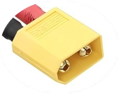
MT60/MT90 battery power connector
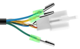
Separate motor phase leads and Hall sensor connector
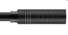
Sealed circular motor connector
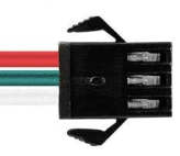
Three-position rectangular signal connector
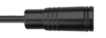
Small sealed circular signal connector
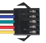
Five-position rectangular display connector
These photos show common connector styles. The same style may be used for different functions on different systems. A sealed-looking housing is not proof of a particular waterproof rating.
What 1T4 and 1T5 wiring harnesses mean
A 1T4 harness has one main connection and four branches; a 1T5 harness has five branches. These can bring display, throttle, brake or other connections together to reduce separate cables. The branch functions and pin assignments still depend on the supplier.
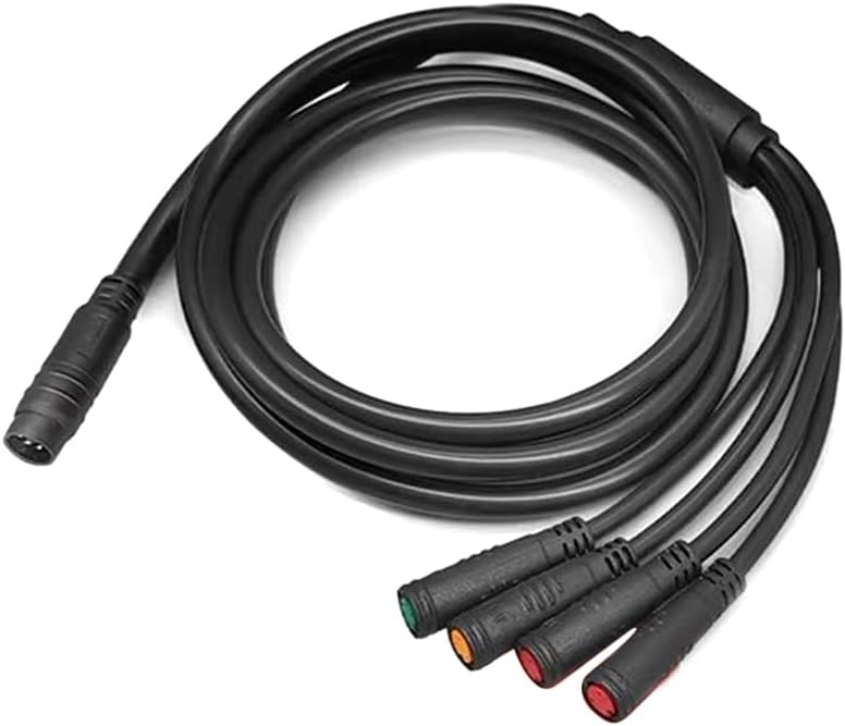
Example of a 1T5 wiring harness. Confirm the function of each branch before selecting a replacement.
Pin count is only the first check
Check the connector series, male or female end, pin count, keying and the function of every pin. Wire colors are not a universal wiring standard. Basic lights may use two wires, while combined lighting, horn or indicator assemblies can require more.
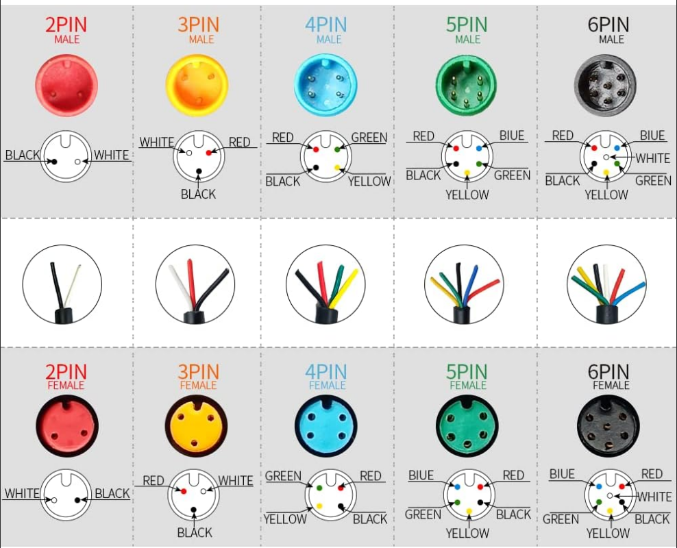
Illustrative connector family with 2 to 6 pins. This image is not a universal wiring diagram; use the wiring document for the exact product.
Common controller functions
Everyday riding features
Connection | Connects to | Main purpose |
Battery | Battery pack | Supplies power to the controller |
Motor | Motor phase wires and sensors | Drives the motor and receives position signals where used |
Throttle | Thumb or twist throttle | Sends the rider’s power request |
Brake | Brake switch or sensor | Requests motor cut-off when braking |
Display | Handlebar display | Exchanges settings, status and assistance commands |
Pedal sensor | Cadence or torque sensor | Detects pedaling or rider effort |
Protection and fault reporting
Depending on the model, protection functions can include brake priority, low-voltage cut-off, current limiting, temperature protection and throttle-fault detection. A compatible display may show an error code to help identify a problem. These features do not replace correct component matching, sound wiring or regular maintenance.
Optional features
Cruise control: maintains a selected setting on supported systems; activation and cancellation vary by model.
Electronic braking: uses the motor system to help slow the bike and does not replace mechanical brakes.
Regenerative braking: returns some energy to the battery only when the motor, controller and battery system support it. Many common geared hub systems cannot provide it without a suitable design.
Anti-theft functions: may include an electronic lock or other supported features.
Parking or kickstand interlock: can inhibit motor drive when the relevant switch is active.
Phone connectivity: can provide status, settings or diagnostics through a compatible Bluetooth-enabled controller, display or module.
Brake cut-off, electronic braking and regenerative braking are different functions. Do not assume that a controller offering one includes all three, or that regenerative braking guarantees a particular increase in range.
How to choose a compatible ebike controller
Match the battery: confirm nominal voltage, permitted voltage range and battery/BMS discharge capability. The battery must support the controller’s intended current demand.
Match the motor: confirm motor type, rated voltage, intended power level and sensor requirements. Ask whether motor parameters need to be configured.
Match the display: check the exact model, UART or CAN connection, protocol version and firmware compatibility.
Match the wiring: verify every connector and pin assignment, including the throttle, brakes, pedal sensor and lights.
Match the installation and features: check housing size, cooling, mounting space, environmental rating and the functions you actually need.
Use a supplier-approved combination and have installation checked by a qualified technician. For a conversion project, a matched kit can make component selection easier. Ecoway’s electric bike conversion kit range provides examples of motors, controllers and displays supplied as a system.
Frequently asked questions
Is a sine wave controller always better
A sine wave controller is often a good choice for smoother, quieter riding. A square wave controller can suit a simpler, lower-cost setup. Motor compatibility and tuning matter more than the name alone.
Can I replace a 15 A controller with a 30 A controller
Only after checking the complete system. Compare the same type of rating first—rated current with rated current, or maximum current with maximum current. The battery/BMS, motor, wiring, connectors and cooling must all support the new controller.
Does a controller with more MOSFETs always support more power
No. MOSFET specification, cooling, circuit design and current settings also affect capacity. Request the actual voltage and current ratings.
Will two UART displays work with the same controller
Not necessarily. UART identifies the connection method, while the message protocol and version determine whether the devices understand each other. The wiring must also match.
Will a matching waterproof plug guarantee compatibility
No. Similar-looking connectors can use different pin assignments, voltages and communication protocols. Verify the exact parts before connecting them.
What information should I send when asking for a replacement
Send clear photos of the controller label and all connectors, plus the battery voltage, motor model, display model and functions you need. If available, include the wiring diagram. These details help the supplier identify a suitable replacement without relying on appearance alone.

